


Q: Bias flow can be set at range settings in one of the given ventilators:
a) Maquet Servo-I
b) GE carescape R860
c) Puritan Bennett™ 840 Ventilator
d) None of the above
Ans is B (GE CARESCAPE R860 Ventilator)
Bias flow on a ventilator refers to the continuous flow of gas that is provided to the patient, even during the expiratory phase of the breathing cycle. During expiration, the ventilator continuously delivers a gas flow (bias flow), which is measured in the expiratory channel. In the Maquet Servo i ventilator, the bias flow is set at factory default values (2 L/min in adults and 0.5 l/min in infants and there is no range settings while in GE CARESCAPE R860 the bias flow can be set as Bias Flow from 2 to 10 l/min and on NIV from 8 to 20 l/min in adult settings .

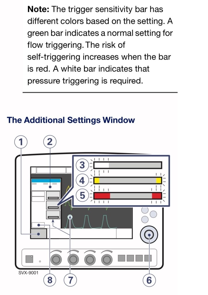
Gas flow through the Patient unit
Refer to the Patient Unit gas flow diagram for the location of the following numbered components:
- Gas inlet for O2
- Gas inlet for air
- The gas flow is regulated by the gas modules for Air and O2.
- The gases are mixed in the inspiratory mixing section.
- The Oxygen concentration can be measured with an O2 cell or O2 sensor.
An O2 cell is shown here.
The O2 cell is protected by a bacteria filter. - The pressure of the mixed gas delivered to the patient is measured by the Inspiratory pressure transducer.
The transducer is protected by a bacterial filter. - The inspiratory channel delivers the mixed gas to the patient systems inspiratory tubing. The inspiratory channel also contains a safety valve.
- The patient breathing systems expiratory tubing is connected to the expiratory inlet. The inlet also contains a moisture trap.
- The gas flow through the expiratory channel is measured by ultrasonic transducers.
- The expiratory pressure is measured by the expiratory pressure transducer (located inside the ventilator). The transducer is protected by a bacterial filter inside the expiratory cassette.
- The pressure (PEEP) in the patient system is regulated by the expiratory valve.
- Gas from the patient system leaves the ventilator via the expiratory outlet. The outlet contains a non-return valve.
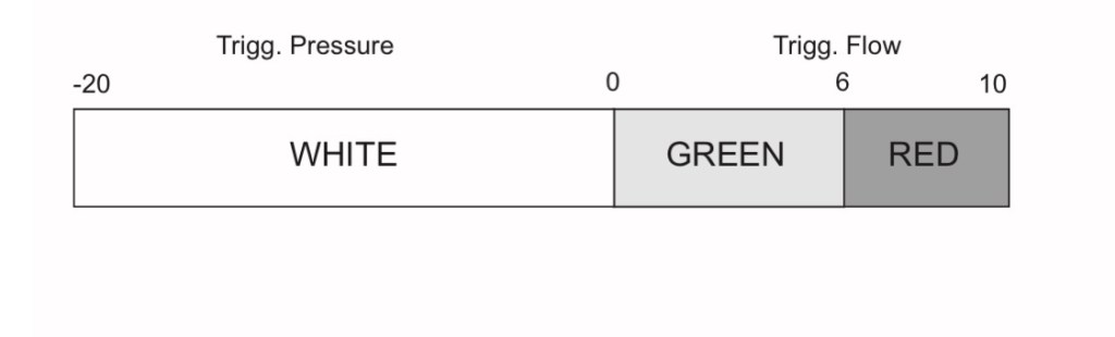
In servo i ventilator , At a trigger sensitivity level above zero (0),The ventilator senses deviations in the bias flow delivered during expiration. These deviations are caused by the inspiratory efforts of the patient. The further to the right on the scale, the more sensitive is the trigger function.
At a trigger sensitivity level below zero (0), the ventilator senses deviations in the pressure below PEEP created by the patient. The pressure below PEEP required to initiate a breath is shown when the setting is made.The further to the left on the scale, the more effort is required to trigger.
Trigger sensitivity
a. Below zero: Trigger sensitivity is
pressure dependant. The pressure below PEEP which the patient must create to initiate an inspiration (cmH2O) is indicated.
b. Above zero: Trigger sensitivity is flow dependent. As the dial is advanced to the right (step wise from the green into the red area) the trigger sensitivity increases i.e the inhaled fraction of the bias flow leading to triggering is reduced.
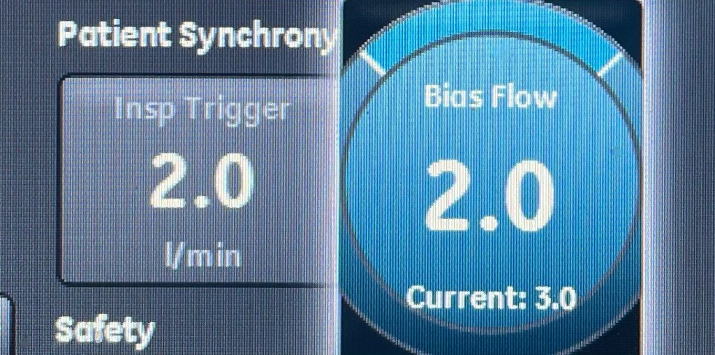
In GE CARESCAPE R680 , The continuous flow that is circulated through the patient circuit during the expiratory phase of the breath cycle. The bias flow may be increased above this setting by the ventilator for some FiO2 settings.
The Bias Flow rate, set by the clinician will be used to maintain PEEP and for the inspiratory phase of the time cycled mechanical breaths. Insufficient setting of the Bias Flow rate may cause an inability to reach or maintain the set PEEP and or inspiratory pressure during the mechanical breaths.
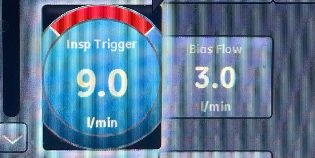


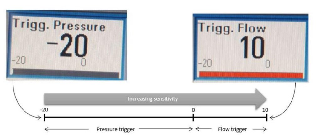
Interestingly, the flow trigger setting should probably be in litres per minute (that, after all, is how we measure flow) but this is not viewed as mandatory by all ventilator manufacturers. For instance, the Puritan Bennett 840 allows the user to set a flow trigger directly, in L/min. In the case below the trigger is set to 3L/min.Thus, in the Puritan Bennett models, setting a lower value of flow trigger (eg. 2L/min or 1L/min) represents an increase in sensitivity, i.e. a lower flow required to trigger a mechanical breath. In contrast, in the Maquet SERVO-i model interface, a decreasing trigger value corresponds to a decrease in sensitivity. Their trigger variable is controlled by the twiddly dial on the ventilator and can be tuned to a range of settings from -20 to +10. This range represents an increasing sensitivity of the trigger, from least sensitive at -20 to most sensitive at 10.
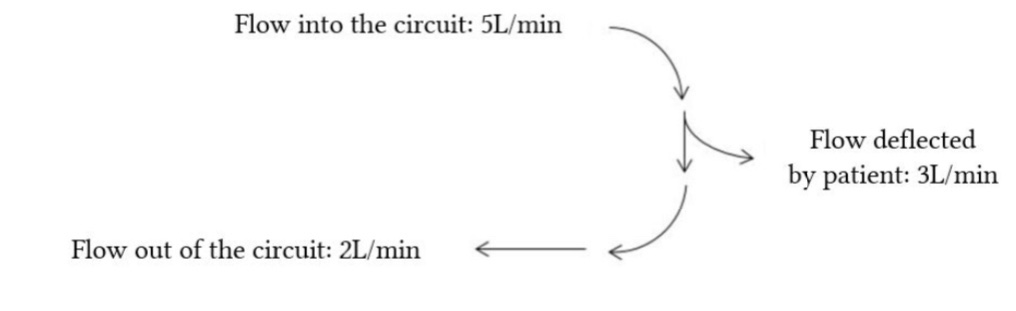
How Bias Flow is used for Flow Triggering : When a patient takes a breath, some of the flow is directed into their lungs. The expiratory flow rate in the ventilator circuit is decreased by this, such that Vin – Vout = x, where x is some “missing” flow measured in L/min. Flow triggering occurs when this missing flow reaches some prescribed threshold value, which causes the ventilator to open the inspiratory valve and deliver a breath. The exact value is susceptible to manipulation via the settings, and the default setting differs between manufacturers, but generally it’s in the ballpark of 1-2 L/min.
For comparison, the normal
mean inspiratory flow rate at rest is probably about 15L/min, with a peak of around 30- 35L/min (Tobin et al, 1983) which makes this a relatively effortless goal to achieve.
To make things more confusing, the range between -20 and 0 actually represents a pressure trigger; the values in this range correspond to a negative pressure in cm H2O, such that a setting of -20 represents a pressure trigger of -20 cm H2O. The range between 0 and 10 represents a flow trigger, and corresponds to a percentage of the bias flow which needs to be “deflected” by the patient in order to trigger the mechanical breath.
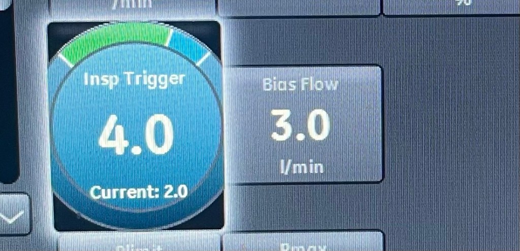
A setting of 0 is the least sensitive flow trigger, and represents a 100% deflection (i.e. the patient must generate a flow equal to 100% of the bias flow though the circuit, or 2L/min). A trigger of 10 is the most sensitive, and represents a flow deflection close to 1% of the bias flow. The default setting of a recently reset/restarted SERVO-i ventilator is a flow trigger of 5, which corresponds to a bias flow change of 50%, or 1L/min.

the bar is green for a normal setting for flow triggering
the bar is red when there is a risk of self-triggering
the bar is white when pressure triggering is selected.
Pressure triggering
Pressure triggering describes a method whereby a decrease in circuit pressure is detected by the ventilator pressure sensors and interpreted as patient effort. The patient inhales against a close inspiratory valve, producing a pressure drop by this effort, and in response, the ventilator delivers a mechanical breath by opening the inspiratory valve. Conventionally, where a pressure trigger is used for a prolonged period, a typical setting would be 1 cm H2O.
